Introduction
Since the announcement of new loads more compact and adjustable by the Arc Système company (see facebook page of AS), there were numerous positive reactions.
Mass and Inertia
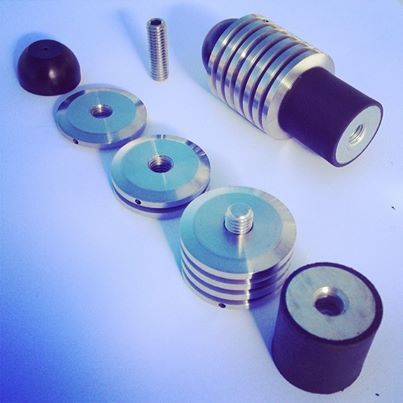
One thing that I would like to address by this short article concerns the inertial properties of two loading configurations: one where the individual loads are spread over a quite sizeable length and one in contrast where the loads are much more packed. Look at the following pictures: on the left this the first kind of configuration where the loads on a sidebar are spreads over 8 inches, whilst on the right the new manufactured loads are packed on a 1 or 2 inches block.
|

|
Take for definitiveness the total mass of the loads in both cases equal to $M$, with the gravity center located at the same distance $R$ from the bow fixation. One can always get a well balanced bow by playing on the sidebar opening angle, but this concerns the static equilibrium of the bow. What happens in the dynamic phase for instance just after the release before the arrow get out the bow window?
Well to not go into the mathematics, one can have an idea of the underlying physical process looking at the current Sochi 2014 Olympic games, especially the figure scatting tournament. Looking at a skater doing a pirouette
After the beginning of the figure, the skater tends to join their arms close to her body. What happens then? The spinning velocity increases. This is what it’s called the kinetic moment conservation. In brief the quantity:
$$ L = I \times \omega $$
Is conserved with $\omega$ the spinning rotation velocity around a rotation axis (the skater in the video exemple), and $I$ the inertia moment of the object in rotation. The inertia moment is defined for a set of loads of mass $m_i$ spinning at a distance $r_i$ by:
$$ I = \sum_i m_i r_i^2 $$
In the case of the skater, the arm play the role of the loads and when they come closer and closer to the body, the $r_i$ decreases, so does $I$ but as $L$ is conserved then it means that $\omega$ should increases, as it is the case, the skater spins faster and faster. The contrary also applies when the arms are put at the horizontal, then $I$ increases and $\omega$ decreases.
In fact, the exact conservation of the kinetic moment is not usually realized but the inertia moment introduced above is a key parameter in the equation of motion of sizable objects. And then, it might be interesting to understand that there are noticeable differences between two configurations of sidebar loading even if we use the same mass $M$. Look at the two cases of the following figure:
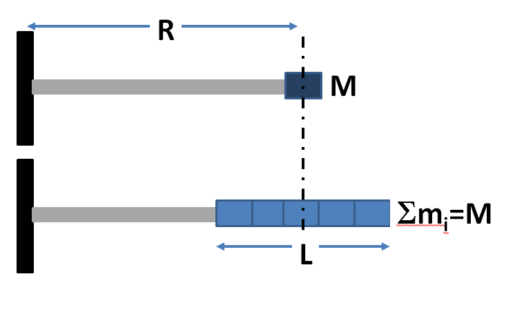
The top configuration (C1) is a schema of a packed loading; its inertia moment is then approximately
$$ I_1 = M R^2 $$
The bottom configuration (C2) is a setup of several ($N$) individual loads of mass $M/N$ spread over a total length $L$ but keeping the center of gravity at the same distance $R$ from the rotation axis than in configuration C1. The direct calculus of the inertia moment is given by
$$ I_2 = \sum_{i=0}^{N-1} m_i r_i^2 $$
With $m_i = M/N$ (independant of the "i" index) and $r_i = R-L/2+L i/(N-1)$.
The expansion of the $r_i^2$ factor, introduces 3 terms:
- The first term is independent of the index “i” and yields a contribution equals to $I_1$;
$$ I_2^{(1)} = M R^2 = I_1 $$
- The second term is linear on “i” and equal to 0, just because of symmetry properties of mass distribution around the center of gravity.
- The thrid term yields a positive contribution
ive suivante
$$ I_2^{(3)} = \frac{ML^2}{12}\left[\frac{2(2N-1)}{N-1} - 3\right] $$
This last term equals the inertia moment of an homogeneous bar of mass $M$ and length $L$ when $N$ tends to infinity.
Well done, so the inertia moment of configuration C2 is equal to the inertia moment of configuration C1 increased by the contribution of the inertia moment of the set of loads as there are spinning around an axis passing by the center of gravity of the set. This is a general result of mechanics that I just demonstrate in the particular example studied for pedagogical purposes. It yields
$$ I_2 = MR^2 + \frac{ML^2}{12}\left[\frac{2(2N-1)}{N-1} - 3\right] > I_1 $$
Let us take an example where $L$ is of the order of $R$, then it is easy to show that spreading the loads tends to increase the inertia moment even if the center of gravity remains at the same location.
Epilogue
Well, so what? Why increasing the inertia moment of a sidebar matter? Remember the skater case, to slow down it spinning rotation he/she just open his/her arms to the horizontal.The bow is harder to rotate if its sidebar has a greater inertia moment.So, if the bow shooter wants the use the new loads in a more packed set, he should either increase the total mass of the set $M$, either increase $R$ (by changing the sidebar length and changing the opening angle to retrieve the equilibrium balance). Using lighter and more spread loads, the tuning is possible by playing with $M$ and $R$ but also playing with $L$ (spreading length) which act on the $I_2^{(3)}$ factor.
So, being enthusiastic by using the new loads is of course a rather natural reaction, and one should thank Arc Système but one should keep in mind the new inertia properties of the new configurations and I would advise not to throw away the old fashioned loads.